Showing posts with label fake components. Show all posts

Wednesday, 8 January 2014

Issues faced by High Reliability Industries such as Defence, Aerospace, Oil & Gas, Automative

Over the past 15 years the electronic industry has been moving away from lead solder due to environmental, health and safety issues. This has reached a point where a vast majority of ICs are only purchased in lead-free format. To enable this transition, lead-free solder was introduced, but the only catch with lead free solder was that it wasn't as good as leaded solder, for instance it melted at a higher temperature than lead solder.

But certain high reliability industries were made exempt from moving to lead-free, as they were operating in  important environments and at the time it was unknown how exactly lead free solder would hold up or perform in harsh conditions. Certain examples are :

Military / Defence - Missiles could be stored long term and then used, due to these extended timelines and the nature of its use it had to be 100% operational, so a risk could not be taken of the solder being lead free as no data was available regarding its long term effects.

Aerospace - Due to the G-force, height, pressure that the aircraft come under, it was as important from the safety standpoint that the aircraft system not to fail mid flight. Lead free solder as with Military / Defence had not proven itself yet to be as robust for harsh environment.

Automative - Due to high heat, vibration and safety issues; critical electronic systems in cars such as braking systems and airbags were also exempt.

Due to such changes in regulations where most of the other sectors had moved on lead free solder, many IC manufacturers have stopped producing leaded parts, they were producing just lead free parts. One factor that hit High reliability industries was that although high reliability parts cost more than commercial versions, in many cases the small volume consumption of these parts in lead form did not justify setting up a separate line to make a lead version of the component, therefore the high-reliability industries often struggle to find their ICs in the lead format.

Automated Retinning, Alloy Conversion , Pb , Sn/Pb

Often they would have to buy them in lead free format and convert them to lead format, there is no credible and safe way to do this for BGA other than Retronix - IC Rescue Process, it is the only process that does not use any reflow cycles to achieve alloy conversion and therefore meets the IC manufacturer's specifications. Another issue that keeps the industry restricted at times is that they rely on tried and tested technology especially for missiles, aircraft control systems as they know it works.At time technology used by certain IC manufacturers for making certain components become obsolete and they stop making the parts altoghether, high reliability industries will end up buying a bulk of components with total guess work anticipating future requirements.

So the issues that they could face are : 
- They may only buy in lead free format which would have to be converted to Leaded version
- They may not be able to find the ICs at all.
- A component is needed which has been out of production and obsolete.
- Forced to buy large volumes of ICs, this could lead to component packages being broken open, a few are used and the rest become exposed leading to oxidisation and solderability problems.

Each of the problems can be solved and can save high reliability industries from having to spend too much time and effort on the ICs, contact us using this link - http://www.retronix.com/contact-us or email us on info@retronix.com

Do visit our website : http://www.retronix.com

A few interesting videos on our processes -


Tuesday, 3 September 2013

Failed PCB's - What happens to the electronic components mounted on them?

It is a fact that there will always be a certain number of failures when PCB's are manufactured and this is normal due to the nature of manufacturing processes. Typical causes that can cause failures are:

1) Paste issues
2) Raw PCB faults
3) Rogue Solder joints

These faults mentioned above are the first indicator that the components mounted on these PCB's may be good, since they have nothing to do with the faults. Therefore in all probability the ICs may be brand new, unused and in perfect working order.

But sometimes company policy states that these failed PCB's be send straight to landfill and recycled, this leaves a lot of potential threats, as certain people with vested interests may get the opportunity to counterfeit these components by using the scrap material from these landfills, also in some cases be sold faulty or completely degraded to unsuspecting customers who buy and implement them in their supply chain leading to  huge problems later to deal with.

  Picture used for representation purposes only
Companies were taking this risk of sending the failed PCBs straight to landfill since there was no safe way of recovering these perfectly good components from PCBs for re-use. However recently there is a process developed that can recover these components for re-use in a very safe manner and without reflow cycles, and this is certainly a much better and economical way to recycle them than to throw the full unit away.

When new components are scarce, as is often the case, their recovery becomes even more important and even more profitable. The risk of dealing in counterfeit components has increased with the 2012 US National Defence Authorization Act. As this global issue becomes more and more of a problem, the ramifications, sentences and fines are becoming increasingly severe. Therefore the best option is to recover this ICs in a safe manner for re-use.

Here is a small demonstration of the process :


By recovering electronic components, up to 50 times the value can be realised from the scrap. The treated scrap, with components removed, could then be sent to any recycler, thereby also eliminating counterfeiting and the re-circulation of faulty and degraded parts.

E   - info@retronix.com, sales@retronix.com

Monday, 22 July 2013

Implementing faulty/counterfeit ICs in the supply chain can be dangerous. What are the options to avoid this?

It is well known that it can be difficult to find a genuine and reliable supply of electronic components particularly when they are scarce or out of production by the original manufacturer. Although refurbished components are sometimes frowned upon for being 'unsafe' and therefore are not a part of the PCB repair process, sometimes this can be the only solution to get around components which are scarce or hard to source.
Especially for a component supplier or broker, the biggest risk is loss of credibility; should a faulty, substandard or counterfeit IC be sold to one of the customers, and hence to avoid or substantially reduce the risk of this to occur; component test is advised. But what are the different tests that can be performed? Listed below are a few of the important tests that are done on a sample or even the whole batch at times to determine authenticity:

Visual Inspection : This is a very effective component testing method, by using optical inspection it can be determined if the components are in good condition, whether there are any damages or any minute defects.

XRF Analysis : This is a non-destructive method to determine what alloy the termination consists of. This is particularly useful for businesses belonging to the high reliability industries such as defence, medical, aerospace, Oil & Gas sectors.

Solderability Test : This test verifies whether the component is re-solderable and also if it is good enough to be placed back on a PCB with reflow.

Electrical Test: Also known as BEST (BGA & Electrical Silicon Test) used to check the electrical parameters of every pin to pin e.g. current, voltage, diode resistivity, and silicon connectivity. 

Key Function Test : Some devices may need tested by creating a circuit to ensure that they are operating as expected. With the help of the component datasheet, a circuit can be created and the key aspects of the IC can be checked. For example MOSFETs can be tested to confirm that they still meet the manufacturer's specifications.

Flash Memory Test / Memory Programming : Components can be programmed to check for counterfeit programmable components. Device ID codes can confirm if the devices were blank or programmed. Already programmed FLASH parts can be erased back to factory default settings.


E   - info@retronix.com, sales@retronix.com
Know more about our IC Tests (Click here)

Wednesday, 17 July 2013

High Reliability industries are vulnerable to counterfeit ICs

High reliability industries such as the Defence, Medical, Aerospace, Oil & Gas sectors rely on electronic parts that are no longer produced by the original manufacturers or even sold by their authorised distributors. That reliance is based, in part, on the long life cycles of these systems. An electronic part may be manufactured for two years, but many defence, medical and aerospace systems which use these parts may be in service for more than two decades. Older components often need to be properly tested and would require retinning to avoid solderability issues like tin whisker.


These high reliability industries are critically dependent on a technology that obsoletes itself every few years or even faster in some cases, is made in locations which are not secure and over which they have no market share influence. 

To source scarce parts, purchasers in these high reliability industries often buy from independent distributors or brokers. This introduces high risk of faulty or counterfeit components being acquired.


E   - info@retronix.com, sales@retronix.com
Know more about our Automated Retinning (Click here)

Tuesday, 18 June 2013

Anti Counterfeit IC Testing : Visual Inspection

As part of the Retronix Anti-Counterfeit IC testing service a customer approached us asking for our level 1 authenticity test, specifically the visual inspection service.

The customer send us approximately 3000 qty - NUD4700 type parts and asked to pick a random sample of 11 for visual inspection to check for authenticity. The reel information and datecodes given were the following: 
Retronix - Authenticity tests
IC Testing services


    Where :
  
    M = Date Code
    MNH = Device Code
    . = Pb-Free Package


Anti-Counterfeit IC Tests

The first check straight away points out certain discrepancies.  Markings do not match the information on the datasheet, and the direction of the text with reference to the Anode was found to be incorrect, further inspection about the device itself revealed the following:
Component Testing services Retronix

As it can be seen from the datasheet image and from the image that is sourced from Mouser Electronics, the bottom side of the device should be connected to the Cathode and continue onto the entire bottom side. But as can be seen with the image of the device on the right that these devices have two isolated pins with the bottom side being the outer casing and not a contact, this shows us that the device in question is not as per standard and is considered suspect.

Continuing investigation of the device for further inspection shows:

Retronix Ltd. IC Tests

Retronix Ltd. Component Testing
1                                              2        

Device contacts are found to be incorrect, Anode and Cathode are formed into a gull wing as can be seen in 'Image 2' and not as they originally should have been as shown in 'Image 1'

Conclusion :

The visual inspection of the sample puts the batch as suspect and cannot be termed original as per standard datasheet and information available about the device. The report along with all photographic evidence and technical information was provided as a report to the customer as suspect counterfeit. This gives the customer a good insight into future purchases from the buyer and also this current purchase which could have caused big issues in case the customer would have gone on and implemented the same into his supply chain.


Are you interested in getting your IC purchases tested and have complete peace of mind? We have a huge range of IC testing services which can be found  here : Tell me more

In case you need to know more about our services and want to get in touch with our test manager then send in your enquiry using our contact us page : Click Here

For more info about Retronix - Click Here
We welcome you to join our LinkedIn group Click Here


Tuesday, 4 December 2012

Retronix Ltd. | Counterfeit Alert 2012 |

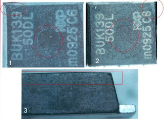
A customer sent approx. 5000 parts [BUK139-50DL] to check the authenticity of the components.  The customer who had procured these parts believed that the devices were originals and worked perfectly fine. He sent these parts to Retronix for Visual inspection, marking permanency testing, de-cap and a basic electrical test.

First a visual check of the label information was done and it showed on the labels attached on each reel, that the parts were lead free. Moving onto deeper visual checks on the components for the markings and the condition of the terminal told a different story. Retronix used the standard IDEA-STD-1010-B to compare the results.


Anti-Counterfeit IC Tests


Images 1 & 2 show faint indent markings and corner damage, these signs are evidence of remarking the components. Moreover there was no country of origin on the devices.

Image 3 shows further evidence that parts are remarked/sanded down as the device is uneven.


Visual Inspection by Retronix


Parts on the same reel showing different DRAIN tab features, also the top part of the device was in a very poor condition


IC tests by Retronix


Further to this, parts from the same reel showed different DRAIN tabs, the condition of the tab was poor, deep scratches and signs of damages to the edge as shown.


The Retronix testing team then went on to perform an X-ray test of these devices for a more in depth look and as per ERAI-STD-1010-B used for as reference found the following:


X-Ray Test by Retronix


XRF testing services


The test revealed that different results of die and the drain tab, all the parts on the same reel with the same datecodes should match under the X-Ray. As was mentioned earlier the labels showed all the devices to be lead free, and in order to authenticate this the X-ray test was performed which revealed otherwise.


IC tests by Retronix

The de-capsulation test was then done on the devices :


De-cap tests by Retronix
Figure : Images illustrate the topside (1) and the underside (2) of the sample device. Analysis suggests no evidence of attempted re-marking or re-packaging.


De-cap tests by Retronix

The images illustrate the package markings (1) , the entire die surface (2), and the die viewed at high magnification (3) and (4) , with no known good component or information from the datasheet, the die could not be confirmed as genuine. If the information on the datasheet is to be compared to the die, then Retronix believed that there would be more internal circuitry. Moreover no Die markings were found showing part number or the manufacturer.

Further checks revealed that the parts were already reported to the ERAI, where complaints such as parts smoking exploding on the boards were being reported.

Conclusion :

With all the evidence found Retronix believed the parts to be counterfeit components and not suitable for use on PCBs due to the electrical tests that were carried out and also with the information found on the ERAI website.

For more info -
Know more about Retronix | CLICK HERE |
Know more about our IC Testing services | CLICK HERE |
We welcome you to join our LinkedIn group | CLICK HERE |
Contact us : | CLICK HERE | info@retronix.com | sales@retronix.com

YouTube | LinkedIn | Twitter


Wednesday, 15 August 2012

Counterfeit Alert: August 2012

W83977ATG (WINBOND)


A customer sent Retronix's testing department a large number of these Winbond W83977ATG components and requested a visual inspection to determine their condition prior to use. The devices were bought as new and unused, but the evidence found by our testing team revealed that the parts were not compliant with standards set by IDEA-STD-1010B, Exhibit 46B Figure 12-79, Coplanarity Failures.

The parts arrived in non-moisture bags, meaning that if they were going to be used, they would need to be baked beforehand to remove any moisture. Some of the components which were visually inspected by the testing team at Retronix also showed signs of contamination. Upon opening the first bag of components, Retronix's testing team noticed obvious damage to the top left component.

Top tray of first bag of components - visible damage to pins on top left device
Top tray of first bag opened - visible damage to top left device.
Closer inspection of the devices uncovered contamination on the back of the component and damage to the pins. 

Left - contamination on back of device. Right - pin damage to device.
Although some of the components displayed differing pin 1 indents, this may have been because the batches had mixed datecodes. This theory would need to be verified by Winbond.

THE VERDICT

Due to the initial results of the visual inspection, as well as the more detailed results - which revealed pin damage and contamination - Retronix's testing team has ruled the components to be in "non-conforming condition."

CS5530AUCE (National Semiconductor)


Retronix's testing department were sent CS5530AUCE Geode components with the request that they be visually inspected before use, much like the above Winbond case. These components were also sold as new and unused. 

But as soon as the testing department opened the box containing the components, they knew that these components were not what they said on the label. As you can see, although these components are on the same tray and have the same markings, they have different pin 1 indents and different top side edges.

The visible differences in the shapes and pin indents of the devices.
Upon closer inspection, Retronix's testing team discovered that the components had several scratch marks on their surfaces and signs of liquid contamination on the solder spheres.

Evidence of contamination and reballing on Geode components.
Left - scratches and evidence of re-balling. Right - liquid contamination on spheres.
 The CS5530AUCE Geode components also displayed evidence of being re-balled.

THE VERDICT


The visual inspection revealed a number of anomalies and the more detailed results of the tests uncovered yet more unusual features in these components, such as scratches and sphere contamination. Accordingly, Retronix's testing team has ruled the components to be in "non-conforming condition."

MPC866PVR133A (FREESCALE)


A customer sent Retronix's testing team a batch of Freescale MPC866PVR133A components and requested a visual inspection to determine their condition prior to use. The devices were bought as new and unused.

When inspecting the packaging that the components had been delivered to Retronix's customer in, the testing team discovered that the label contained no manufacturer information or logo. 

Packaging label with missing information and logo
Packaging label is missing manufacturer's logo and information.

The components were then removed from the packaging and examined visually. This inspection uncovered a problem in the device's solder spheres - the spheres were scratched from underneath.

Devices show scratches beneath solder spheres
Visual inspection at Retronix uncovered scratches beneath solder spheres.
The only way that scratches beneath solder spheres can occur is if the solder spheres have been removed, meaning that it is very likely that this component had been re-balled - despite the fact that it was sold to our customer as "new and unused."

Further testing by Retronix also revealed that the device's solder spheres had evidence of contamination. Unfortunately, this was not the last of the component's flaws - the tests also showed that different sizes of solder sphere had been used to reball the device.

Solder sphere contamination and different sized solder spheres
Left - solder sphere contamination. Right - different sphere sizes used.
Solder sphere contamination is a tell-tale sign of a suspect device - as is different sized solder spheres.

THE VERDICT


Solder sphere contamination is a tell-tale sign of a suspect device - as is different sized solder spheres. This, coupled with the poor packaging which the components arrived in, has led Retronix's testing department to the conclusion that these components are "suspect counterfeit."

Worried about the authenticity of your components? Retronix can help

Monday, 25 June 2012

Counterfeit Alert: June 2012

LSI53C1000R (LSI)


During the initial visual inspection, our testing department became suspicious straight away - the manufacturer's name was spelt incorrectly on the components and the date codes were varied when they should not have been. The markings, which should state "LSI LOGIC," actually say "LSI LOGIG." Our Test Manager, Joe Maguire, contacted LSI about the components and they responded with:

Markings display "LSI LOGIG" rather than "LSI LOGIC."
"Sample parts of the LSI53C1000R that we have on hand in the quality archives show the part marking to only include the word 'LSI' - not 'LSI LOGIC'... There is nothing on file for a correction of the markings from LSI LOGIG to LSI LOGIC."


Further examination from Retronix's testing department revealed that the components had chipped edges, fibre contamination and scratches under the solder spheres - all tell-tale signs of counterfeiting.

Retronix's testing department discovered fibre contamination in the components.
To confirm their suspicions about the authenticity of the parts, our testing department carried out XRF tests. The XRF analysis results showed that all of the components tested had a Pb (lead) content of over 24%, meaning that they were leaded and not RoHS compliant.

THE VERDICT

The results of the visual inspections and XRF analysis, along with LSI's statement, led Retronix's testing department to the conclusion that the parts should be regarded as "suspect counterfeit."

GM71V65163CT-3 (HYNIX)


Visual inspections revealed that two of the Hynix components tested had different textures - one had a smooth surface and reflected light while the other was bumpy and dull in its appearance.

Following this discovery, the testing team at Retronix subjected the components to permanency marking tests. Using a mixture consisting of one part IPA and three parts mineral spirits, a wipe test was performed. This resulted in a slight fading of the markings.
Markings changed from "Hyundai" to "Hynix."
Wipe testing using acetone uncovered another issue with the components - the date codes had been altered. The acetone wipe test also proved that the components had been re-marked. Changing date codes and branding is another trick used by counterfeiters to mask the origins of inauthentic parts.

Hynix were formerly Hyundai, however these may have been rebranded by counterfeiters  in an attempt to pass them off as authentic.

THE VERDICT

Due to the differences in surface appearance between components and the altering of the date codes and branding, Retronix's testing team has classed these as "suspect counterfeit."

MT29F08G08AAWP (MICRON)


Upon initial inspection, there are no obvious attempts at re-marking or re-packaging. However, Retronix's testing team notes that the markings on the die are Intel, not Micron. 

After further investigation through de-cap testing, it is discovered that while the device is marked as a Micron 8GB device, the die is marked as an Intel 16GB device. Furthermore, the date code on the device is 2009, week 16, while the date code on the die is 2008.

The true origins of the device are revealed through de-cap testing.
Retronix's testing department then used a programming software which is compatible with the MT29F08G08AAWP device to determine its unique ID code. This is a simple test which any genuine component would easily pass. The results proved that the device code was not authentic.
After contacting Micron about the component, our team received the following statement, confirming their suspicions about the device:

"The Micron part number is for an obsolete product and the die inside the package is for a different part."

THE VERDICT

Although this component did not display any external signs of tampering, the de-cap testing and incorrect ID code - along with Micron's statement - have allowed Retronix to confirm that this component is most definitely a counterfeit device.

Worried about the authenticity of your components? Retronix can help